Controlling Big Things with Small Things
We often need to control big things with a small microcontroller. This tutorial lays out the options available, their pros and cons, and how to design them.
Welcome to the first tutorial post! It’s a topic many people have asked me about, so I thought why not make it into a tutorial? It’s something I’ve spent a lot of time learning the hard way, and in the end, it’s actually pretty simple!
It’s about switching loads. We have a tiny microcontroller. Maybe an Arduino (AVR), or if we are really (un-)lucky, a 14nm FPGA that can only do 1.8V IO and can barely handle any current. And we need to control a 5A heater with it. Or maybe a 240V fan. Or a powerful motor for our robot. What do we do? There are many options.
Direct Drive
The simplest option, if the load is small enough, is to connect our load directly to the digital output. We can find the maximum current rating of IO pins in the datasheet of the microcontroller. Do not use it for inductive loads (motors, solenoids, relays, etc), because inductive kickback from switching will destroy the IO pin over time. Realistically, that means we can drive LEDs and not much else.
For example, let’s say we are using an Arduino UNO (Atmega328P, Datasheet).
At first glance, it may seem like the maximum DC current per I/O pin is 40mA:
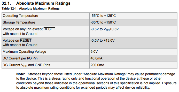
These are absolute maximum ratings, and exceeding them will almost certainly permanently damage the device. However, like the note tells us, the device isn’t actually designed to work up to these limits.
What maximum current the chip IS designed to do isn’t very obvious, but in the notes under “Common DC Characteristics”, there’s this little gem:
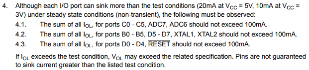
If the operating characteristics are not guaranteed beyond the test condition (20mA), it’s probably a good idea to stick to 20mA. Coincidentally, this is why Arduino recommends max 20mA per I/O pin.
Now let’s look at our load. Let’s say we are using this nice little green LED (Datasheet).
From the datasheet:
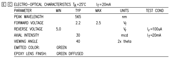
LEDs, like all diodes, have a more or less fixed voltage drop regardless of current through them when they are conducting (also known as”forward biased”). Here we see that the test condition happens to match what we care about (20mA), so that’s convenient. It lists forward voltage as 2.2V typical at 20mA.
Now we can finally calculate how big of a resistor we need:

And the circuit would look something like this (Option 1):
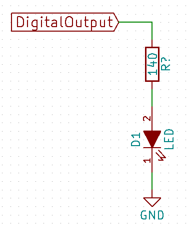
Or we can flip it around and do this (Option 2):
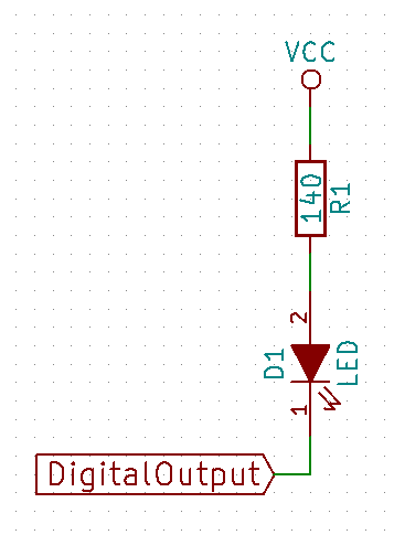
Difference being that with Option 1, the microcontroller sources current when the LED is on, and in Option 2, the microcontroller sinks current when the LED is on. For Atmega328P it doesn’t seem to matter, but many chips have asymmetrical IO drive strengths, which means they are better at either sourcing or sinking current. In that case one option would be better than the other (for many chips, Option 2 is better).
Also note that the resistance value we got here is a minimum. For indicator LEDs, I found that 470Ω usually works well, and sometimes even 1KΩ if it doesn’t need to be visible under direct sunlight.
MOSFET
For devices that are more demanding, MOSFETs are usually the first thing I reach for.
I would say this is what I end up using 95% of the time. MOSFETs (metal-oxide-semiconductor field-effect transistors) are cheap, efficient, fast, small, and relatively easy to use. They are good for DC devices up to about 20A.
This includes things like LEDs (from 25mA indicator LEDs to 2.5A lighting LEDs), DC motors, DC lights, heating elements, piezoelectric buzzers, and even speakers if you don’t mind terrible sound quality.
MOSFETs are essentially voltage-controlled switches. There are two types of MOSFETs – N-channel MOSFETs and P-channel MOSFETs. We will focus on N-MOSFETs here because they are usually easier to drive with lower voltage outputs, and they are usually also more power efficient due to their construction, compared to complementary P-MOSFETs.
Minimal circuit looks like this –
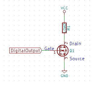
When DigitalOutput is high, the MOSFET conducts and completes the circuit. When DigitalOutput is low, the MOSFET doesn’t conduct. When a MOSFET is conducting, it behaves like a resistance up to a certain current limit (we call this the linear region), beyond which the resistance rises rapidly to maintain constant current regardless of the voltage across it (we call this the saturation region). When we use a MOSFET as a switch, we want to stay in the linear region, where it behaves like a resistor. And ideally we want that resistance to be low.
The controlling terminal is called gate, and the conduction terminals are called drain and source (2 and 3 respectively in the diagram above).
MOSFETs are very complicated devices, but there are really only a few things to watch out for when choosing a MOSFET for basic applications:
- Rds(on). Drain to source resistance when the MOSFET is turned on. This figure is in the datasheet. Too high an Rds(on) means the MOSFET will dissipate a lot of power, which means it won’t be efficient, and we’ll have to deal with the heat.
- Vgs(th). The gate to source threshold voltage required to turn the MOSFET on. For older MOSFETs this will be on the order of 8-12V, which means they cannot be driven directly by a 3.3V or 5V logic output. Many newer logic-level MOSFETs can be switched at 5V and some even 3.3V.
- Vdss (drain-to-source breakdown voltage), this is basically the maximum voltage we are allowed to switch with the MOSFET.
- Advanced: If we need to switch the MOSFET quickly, for example for PWM, it’s important to look at the gate charge figure. The gate of a MOSFET is essentially a capacitor, and it will take time to charge and discharge. The Qg (total gate charge) number divided by the current capacity of the gate driver is approximately the amount of time it will take to charge/discharge the gate. This should be at most 10% of the PWM period. If it’s too slow, add a gate driver for higher drive strength, or pick a FET with lower Qg (there is a Rds(on) vs Qg tradeoff).
- Advanced: MOSFETs behave like a diode from source to drain. This is called the “body diode”. This is basically a high current diode you get for free with every MOSFET, and can be useful in some applications. Operating characteristics of this body diode are usually specified in the datasheet.
- Advanced: If you are using an external gate driver powered by a higher (>12V) voltage to get faster/higher voltage switching, be careful to not exceed the MOSFET’s Vgs(max) rating. That’s often much lower than Vdss. A lot of times this means you need to have a separate voltage rail just for gate switching.
For example, let’s say we want to drive this motor (Datasheet) with an Arduino.
The system is 12V (since that’s the voltage rating of the motor), and the motor has a stall current of 2.4A, which is the maximum current we are expecting to see. For more powerful motors it’s often not practical to spec parts for continuous operation at the stall current, and we have to figure out how much the motor will actually draw in the specific application which depends on torque requirements. But 2.4A is pretty manageable, so let’s use that.
For the MOSFET, instead of just suggesting an option, let’s walk through how I would pick one out of the tens of thousands of options on the market. I am using Mouser, but Digikey, or any other electronic components store selling to engineers will have a similar search engine.
First go into “Semiconductors” -> “Discrete Semiconductors” -> “Transistors” -> “MOSFET”. Now we are presented with 18,990 products, and 19 ways to filter them.
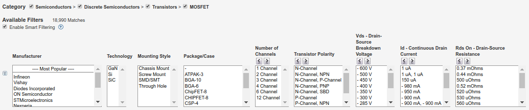
It may seem a bit daunting, but keep in mind that we don’t need to use all of them. Usually using a few is enough to filter the selection down to a manageable level.
Let’s apply these constraints (one at a time):
- Mounting Style => Through Hole
- Number of Channels => 1
- Transistor Polarity => N-Channel
- Id => Everything above 3A
- Vgs(th) => Everything below 4V (but not negative – that’s for P-MOS)
- “Gate-Source Voltage” (max) => Everything above 15V
Now we are down to 1794 options remaining. That’s still a lot, and it’s because our requirements are very easy to satisfy in this case. Let’s be pickier then, and add “Rds(on)” < 50 mOhms. This way we know we won’t have to worry about cooling the MOSFET.
Let’s also choose TO-220-3 package, because we don’t want it to be too big, and we know it doesn’t need to be with our modest requirements.
Now we are left with 268, and we are out of things to be picky about!
So let’s sort by price in ascending order, and look at the first option.
At the time of this writing, the cheapest option that is both in stock and has a datasheet is IRL8721 (Datasheet) from Infineon Technologies (one of the biggest MOSFET manufacturers after their recent acquisition of International Rectifier), so let’s use that.
Since we have filtered by most of our requirements already, at this stage it’s mostly just double checking. Most of it is obvious (Vds(max), Vgs(max)), but there’s on graph that’s very important, and will tell us almost everything about how the MOSFET will behave in our circuit. It’s Figure 1 on Page 3. It gives us the relationship between Vds and Ids at different gate voltages. Remember that Vds / Ids is the resistance of the MOSFET’s switching channel.
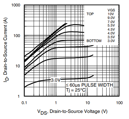
Since there’s no 5V curve, we look at the 4.5V curve (4th from the bottom) since that’s a lower bound. We see that the “knee” starts at roughly 0.7V / 50A. This tells us two things:
- We should not exceed 50A, where the MOSFET goes into saturation and will become current-limiting. We are nowhere near this.
- Below 50A, the MOSFET has a resistance of about 0.7V / 50A = 0.014Ω.
That means when the MOSFET is on and the motor is stalled, we will get a drop of 2.4A x 0.014Ω = 0.034V, and the MOSFET will be dissipating 0.034V x 2.4A = 0.081W of power. That’s nothing to worry about. It won’t even be warm to the touch. We will discuss thermal management in a later tutorial, but a general rule of thumb is anything below 0.5W in TO-220 will not require cooling.
So it looks like the MOSFET is suitable. Let’s design it into a circuit!
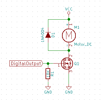
Note that I’ve added two components here:
- R1 is a pull-down resistor. It gives the circuit a well-defined state while the microcontroller powers on (or is held in reset for whatever reason) and isn’t driving the pin. Otherwise the gate will float, and can take on any voltage depending on what’s happening around it. That can lead to the MOSFET being partially turned on or go into oscillation – both can lead to destruction. On an Arduino with a bootloader, the boot-up period can be as long as a few seconds – that’s ages in the digital world and more than enough time for the FET to (literally) blow up. Value of the resistor should be high to limit power consumption, but the exact value doesn’t matter much. I always use 10K.
- D1 is a flyback diode. We need it here because a motor is an inductive load, which means we will get a voltage spike on the drain (pin 2) of the MOSFET when the MOSFET tries to switch it off because of energy stored in the magnetic field in the coils. The diode gives the motor a path to dissipate the energy. A detailed discussion of flyback protection is way beyond the scope of this tutorial, but a 1N4004 will work in most situations. It’s needed when ever we switch an inductive load (motor, solenoid, relay, etc). Without the diode the circuit will work at first, but over time (minutes to years) the voltage spikes will destroy the MOSFET.
That’s it for MOSFETs!
Relays
Relays are another way to switch loads. They are electromagnetic devices each consisting of both a solenoid/electromagnet and a physical switch. Energising the solenoid can either open or close the switch.
Their main use is in switching high voltage and/or AC loads. For example, if we want to control a mains-powered heater with a 5V logic output, a relay would be the most appropriate choice.
They can be used to switch low voltage DC loads as well just like MOSFETs, but they have a few important disadvantages compared to MOSFETs:
- Relays are very slow. 10Hz is roughly the fastest a typical relay can be switched at. On the other hand, a properly designed MOSFET circuit can be switched at >10MHz. That means modulating a relay isn’t really an option with a relay.
- Relays have much shorter lifetimes, on the order of <100K actuations before they wear out either electrically or mechanically. MOSFETs do not have any moving part, and therefore have more or less unlimited lifetime if they are kept cool and operated within limits.
- Relays are harder and less efficient to drive, since they require a continuous current flow to keep the switch actuated.
- They have a minimum load, below which they won’t conduct. This is because of electrical wetting.
- Relays also have higher conduction resistance than high current MOSFETs.
- They make audible clicking noises when opening and closing.
- They “bounce“. When a switch closes, it will bounce (oscillate) a few times in quick succession. If the controlled device is sensitive to this (eg. it counts how many times it has been switched on), this needs to be taken into account.
Use a MOSFET if possible.
A typical relay circuit looks like this:
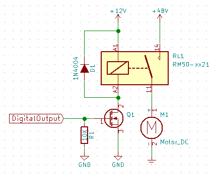
Note the use of a MOSFET to switch the relay. It may be possible to drive a relay directly with a microcontroller pin if the relay has a low enough coil (actuation) current, but I don’t recommend it because relay solenoids are inductive, and will send voltage spikes back to the microcontroller.
Advanced: If you know what you are doing and want to try this, it’s probably a good idea to use a Schottky diode so that the microcontroller’s internal ESD protection diodes won’t need to survive the current spikes, since ESD protection diodes are usually not rated. Note that switch off will be very slow in that case due to the low forward voltage of the Schottky diode.
Warning: do not play with line voltage unless you have received appropriate training and know exactly what you are doing! It can easily kill you. I have been designing and building electronics for 7 years now (and have a degree in electrical engineering), and still don’t think I know enough to safely play with line voltage.
A safer way to control mains-powered devices is enclosed relays. Unfortunately there aren’t many choices there, and I only know of that one product, and it only supports American outlets.
Turning Things On Halfway? Pulse-Width Modulation
If we need to turn something on at less than 100% power but can’t change the voltage easily, pulse-width modulation (PWM) is the typical solution.
It’s a fancy name for “turning it on and off very fast, and control the fraction of the time it’s on”.
Eg. If, in every millisecond, we turn a device on for 100 microseconds, and off for 900 microseconds, it’s almost equivalent to running it at 10% the voltage. The percentage of the time it’s on is called “duty cycle”. In this case the duty cycle is 10%.
This works for DC motors, LEDs, light bulbs, resistive heating elements, etc. Advanced: It’s also possible to do it on AC, but it’s much more complicated and usually requires synchronizing to AC cycles. Look into TRIACs if you are interested in this.
For LEDs, this works because human eyes can’t respond that fast and will “average” the brightness for us. For motors this works because mechanical devices cannot respond that fast. Same for light bulbs and resistive heating elements. Some motors will fail to start below certain duty cycle.
All microcontrollers have hardware support for PWM. For example, the extremely poorly named analogWrite() function in the Arduino library performs PWM.
There are two main concerns in choosing a PWM frequency – how fast we can switch the load, and whether there will be audible noise.
How fast we can switch the load (assuming we are using a MOSFET) is dependent on how fast we can charge and discharge the gate capacitance of the MOSFET, which is a function of the MOSFET as well as drive strength of the gate driver. We usually want the switching time to be at most 10% of the PWM period, preferably even lower. Using the example above with an Arduino driving a IRL8721 FET, we have a total gate charge (Qg) of 8.5nC from the datasheet, and Arduino drive strength of 20mA.


That means we should stick to below 235 kHz.
Audible noise is another problem – when doing PWM on a motor, the coil will vibrate at the PWM frequency, and if the PWM frequency is in the audible range (20 – 20,000 Hz), there may be an audible buzz. It’s best to go above 20 kHz when driving a motor. Unfortunately, Arduino’s default frequencies are 490 Hz and 980 Hz, which are very low, and I’m not sure if there’s an easy way to change that.
Other Options
There are many other options that are outside the scope of this tutorial, but may be helpful if you have very specific requirements –
Bipolar junction transistors (BJTs) – similar to MOSFETs in applications, but current-controlled instead of voltage-controlled.
Insulated gate bipolar transistors (IGBTs) – for very high current DC applications
TRIACs – for switching AC loads synchronized to AC cycles.
Solid state relays (SSRs) – similar to relays, but have both advantages and disadvantages compared to its mechanical sibling.
Happy making!