UnnaturalLight – Part 2: Electrical Design
Blinking a few LEDs… how hard can it be?
As it turned out, harder than I thought it would be! As the LEDs draw about 1W each, and I am using 48 per lamp, thermal management is the main challenge.
The desired function is simple enough – a controller that reads from two potentiometers to get brightness and colour temperature settings, calculate PWM levels for each set of LEDs (one set at 6500K, and one set at 2700K), and drive those LEDs.
Design
The design consists of an Arduino controller, and 3 custom PCBs – an Arduino shield with all the switching circuitry, an aluminum LED carrier, and a small board to be mounted on the front panel with the potentiometers.
Arduino Controller
I decided to use Arduino for now because I want to extend the project to be WiFi-controlled in the future, and I have already designed an Arduino-compatible STM32-based board with WiFi functionality, that I can swap in when ready. The task here is very simple, so virtually any microcontroller will do for now.
Switching Shield
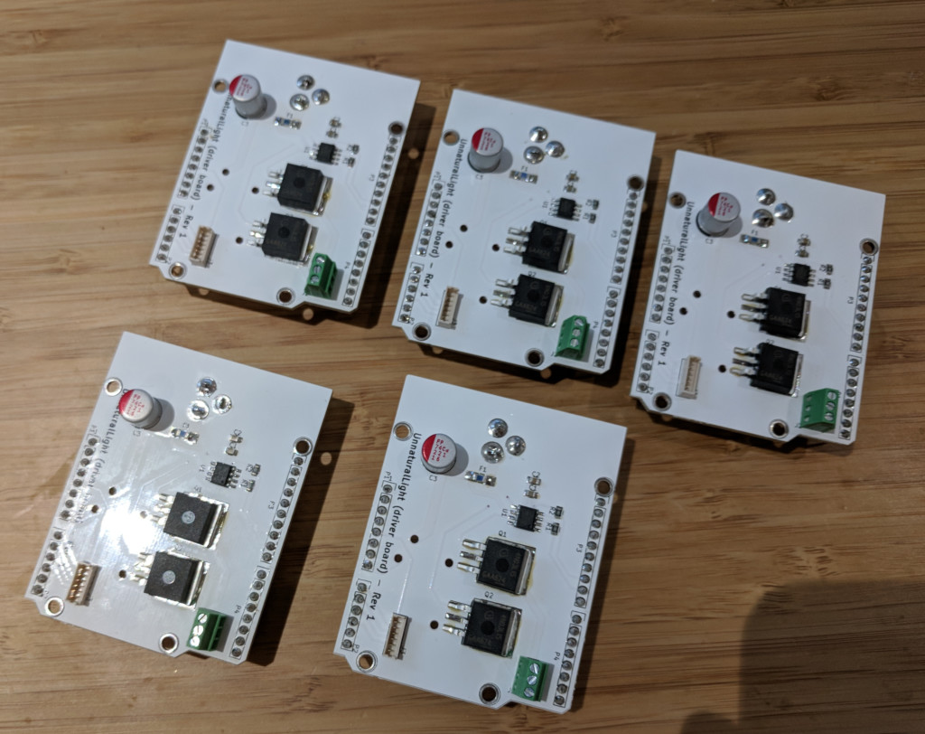
The design is 1 MOSFET for each channel, with a gate driver to make sure they switch fully and quickly. Given the very low Res(on) logic-level FETs I used, the gate drivers probably aren’t necessary especially with an Arduino with 5V I/O, but I included them anyways because I’ll be switching to STM32 chips in the future with only 3.3V I/O, which would result in the FET not being as fully on, hence higher Rds(on) and higher power dissipation. Adding driver chips is much cheaper than adding heatsinks for the FETs. The drivers also reduces switching losses and let me use very high PWM frequencies. Why do we want a very high PWM frequency? Read on to find out!
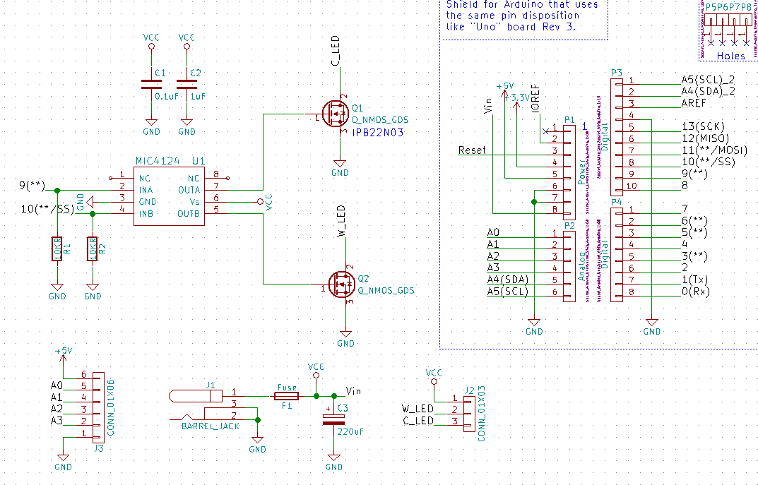
Switcher schematics
One design decision I regret here is putting the bulk filtering capacitor behind the fuse (see below). My first prototypes suffered an interesting problem – if I plug everything in before turning the outlet on (outlets in the UK all have independent switches), everything works. However, if I have the power supply already powered when I plug it into this PCB, the fuse will blow right away. I eventually realised that it’s because in the first case, voltage ramps up slowly as the power supply’s internal output capacitor gets charged up, which also charges my on-board capacitor up gradually. In the second case, the input voltage is already at a full 12V when I plug it into the PCB, which means a high instantaneous current draw to charge my capacitor. This blows the fuse. I worked around it by switching to a smaller capacitor, which is not optimal because that means higher current ripple from the power supply, which reduces the lifetime of the power supply. I will put the capacitor in front of the fuse next time.
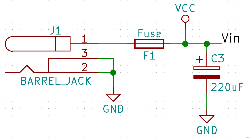
Bad capacitor placement relative to fuse.
I am using an additional barrel jack on the shield because I don’t want all the current for the LEDs (~3A) to go through the header pins from the Arduino. The shield supplies power to the Arduino through Vcc pin.
Aluminum LED PCBs
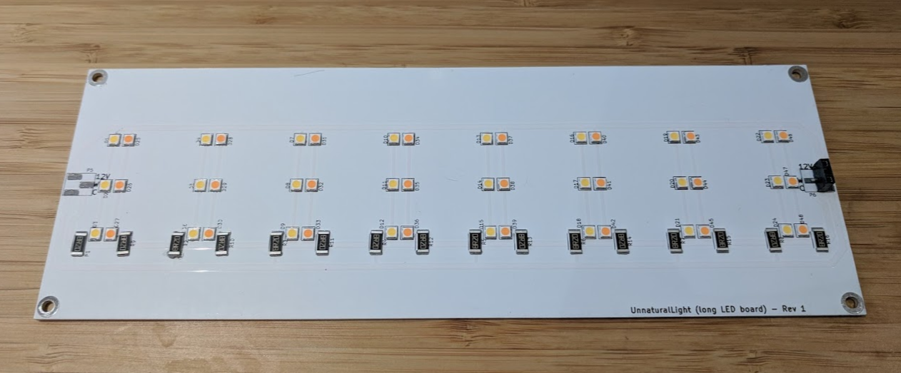
I considered buying off-the-shelf LED strips, but in the end decided to design my own PCBs for flexibility. LED strips typically have low power density due to thermal constraints, and I really want each cool LED to be paired with a warm LED in close proximity for seamless colour mixing. Seeed Studio now offers aluminum substrate at prototyping quantities, and I’ve decided to use that because while they aren’t cheap, their better thermal conductivity means I don’t need to add heatsinks, and heatsinks are very expensive at prototyping quantities, too, at the power levels we are talking about. The board may seem quite a bit larger than necessary – that’s for heatsinking.
Normal PCBs are stacked like this (assuming 2 layers):
--------- Silkscreen -----------
--------- Solder mask ----------
--------- Copper ---------------
--------------------------------
|         FR-4                 |
--------------------------------
--------- Copper ---------------
--------- Solder mask ----------
--------- Silkscreen -----------
Where aluminum substrate PCBs look like this (single layer):
--------- Silkscreen -----------
--------- Solder mask ----------
--------- Copper ---------------
--------- Thin insulation ------
--------------------------------
|         Aluminum             |
--------------------------------
This is my first time making a PCB with aluminum substrate, and here are the things I learned:
- Everything has to be surface-mount. They restrict aluminum PCBs to single layer, and it may be tempting to have thru-hole parts mounted on the opposite side. That doesn’t work because holes aren’t insulated. All the component legs will be shorted to each other through the substrate. My first prototype had thru-hole headers. That didn’t work. This also explains why they restrict aluminum PCBs to single layer – it’s not very useful having 2 layer boards when you can’t have vias! Mounting holes are fine, but they won’t be insulated.
- Everything needs to be reflow-soldered. You know how it’s difficult to solder things to a solid ground plane? Now imagine it’s a 1.6mm thick huge chunk of aluminum carrying heat away instead of just 35 μm of copper. I have a 70W soldering station, and couldn’t get any solder to melt on the board even if I leave the iron in contact with the board for a few minutes. There is no reworking by hand. If you want to change anything, it’s going back into the oven (or skillet).
The actual LED chips I used are from Yuji. This one. Yuji is a niche high-end LED manufacturer making very high CRI (*1) LEDs usually used in photography. They aren’t cheap at about $0.80 each (I use 48 per board), but it’s actually very hard to find reasonably-priced power LEDs at prototyping quantities. My first prototype used Cree XLamp MX-3, which worked, but was slightly more expensive, and has lower CRI. I initially picked the Cree because it’s possible to hand-solder, but then I realized I am doing 48 per board… I am not going to hand-solder them anyways.
*1: Colour rendering index, which is a measure of how well the frequency spectrum matches that of a black-body radiator like the sun. This basically tells us how “vibrant” and balanced colours of objects lit by the light source will look.
User Interface
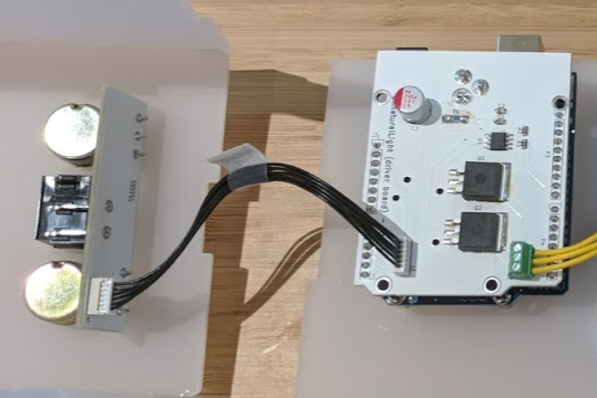
Simple board with 2 potentiometers and a rocker switch, all connected to the driver board through a Molex 6-pin cable. Why switch? Because I want to make them WiFi-controlled in the future, and the switch would enable local manual override.
Soldering
All the soldering was done using a £23.99 (as of this writing) toaster oven. I used to be a big proponent of reflow soldering using electric skillets, and had done that for a long time, but I decided to switch to toaster ovens because skillet reflow heats the solder paste through the FR-4 substrate (which is a good thermal insulator!), which means the substrate has to go to at least reflow temperature (about 225C for leaded solder), and some parts probably go much higher. FR-4 has a glass-transition temperature of 130-140C, and even high Tg FR-4 only goes up to about 190C. Heating it above those temperatures may have an effect on the mechanical and electrical integrity of the substrate, although I don’t think it has been well-studied.
People do all sorts of fancy things with toaster oven reflow soldering with custom controllers, etc. I find that just looking at the thing also works. I look at some pasted area and wait for it to turn shiny under max heat, wait 10 seconds longer, then turn off the oven and open the door. Be careful not to jerk the board, as all the solder paste is still liquid at this point. As it turns out, with cheap ~1kW toaster ovens, this often gets pretty close to the standard reflow temperature profile.
As for the stencil, I bought some 125 micron Mylar sheet, and laser cut them. I find the result to be a bit better if I shrink solder paste layer pads a bit. In KiCad, it’s under Dimensions => Pad Mask Clearances, and I set “Solder paste clearance” to -0.005 inches. Then File => Plot => DXF (be sure to plot the paste layer, NOT front copper), and cut that file on the laser cutter at a very low power setting. If you don’t have access to a laser cutter, you can also use a vinyl cutter. If you don’t have a vinyl cutter either, many companies will do the cutting for you (eg. Pololu).
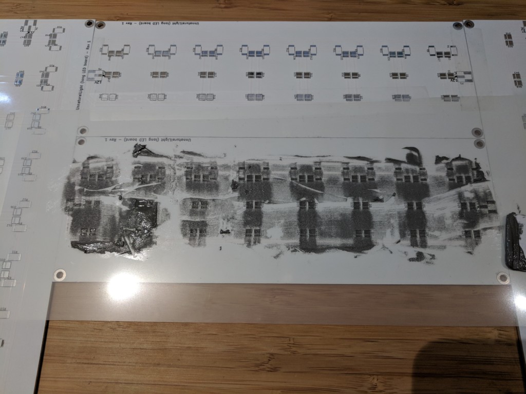
Paste printing using a laser-cut mylar stencil.
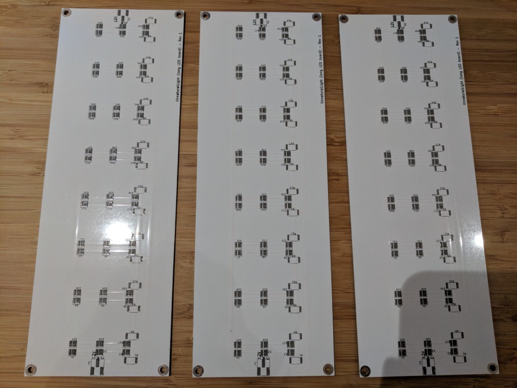
3 boards at once!
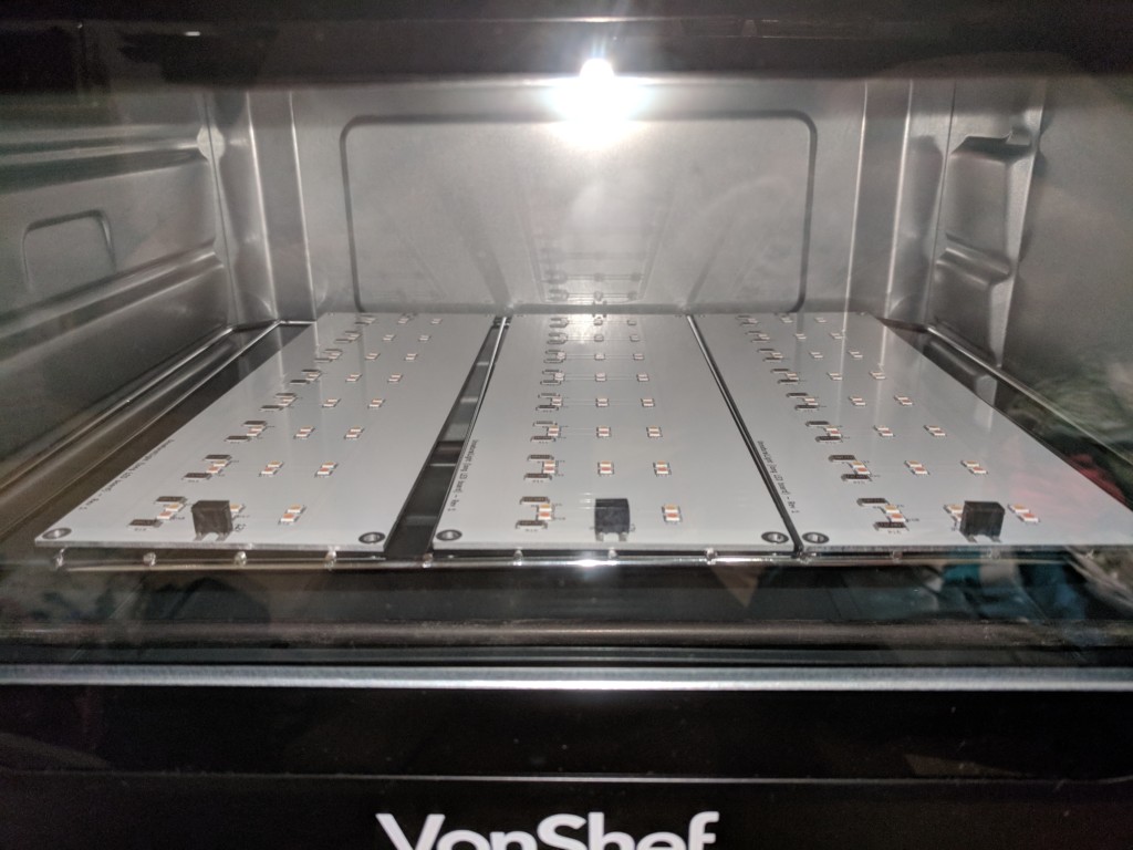
In the oven.
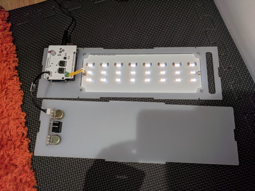
Assembled and tested!
Firmware
Nothing too fancy here. The firmware consists mostly of reading the two potentiometers in a loop, and adjusting PWM duty cycles to the arrays of LEDs. There is some hysteresis to stop flickering if the potentiometer happens to be at ADC LSB boundaries (voltage thresholds where the count goes up/down), and some saturation because I like having full-off and full-on regions in the range. One interesting thing to note is that the default Arduino PWM frequency is 490 Hz, which is fast enough for humans to not detect flicker, but not quite fast enough for cameras!

Significant banding at 490 Hz
This is because most modern digital camera sensors are CMOS, and CMOS sensors read pixels row by row, unlike CCD or even old school film, where there’s a global shutter that synchronises the sampling of all pixels. It looks like at the scanning speed my camera was working at given this lighting condition, the light actually turns on and off about 14 times in the time it takes for the sensor to read the whole array. This is clearly not ideal because I am a millennial and must be able to take pictures at home.
Fortunately this is easy to fix: just increase the PWM frequency. Through simply changing the timer prescaler, I was able to increase PWM frequency to 31.25 kHz (the highest the Atmega328p can do). See code for details. There is no visible flicker/banding at this frequency.
Look ma, no flicker!
There is actually another solution that I didn’t explore – making it slower! As it turned out, LEDs are not the only light source with a flicker problem. Fluorescent tubes (including CFL) also flicker at the line frequency (50/60Hz, depending on where you are). We don’t see it because camera firmwares have workarounds for that (ever wondered what “anti-flicker mode” means on your fancy camera? This is it), but the workarounds are hardcoded to support 50/60Hz only. So theoretically we can take advantage of that by slowing PWM down to 50/60Hz. I don’t like this solution because some humans can actually detect 50/60Hz flicker, and it gives them a headache. Also, why support a workaround when we can solve it in a clean way?
The downside of high PWM frequency is higher switching losses in the transistors. Transistors only dissipate significant amount of power at switching time, so heat losses in transistors is proportional to PWM frequency. Make sure you have a powerful gate driver if you want to do this. Double check with an oscilloscope on the gate to make sure the edges are still nice and clean.
Next up: I am renting at the moment, but when I buy a flat in a hopefully near future, I want to build these lights into walls and ceilings, since having bright light sources so low induce headache and fatigue. This project is really more a proof of concept.
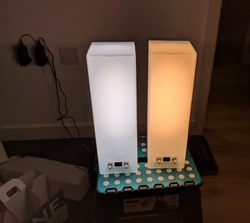
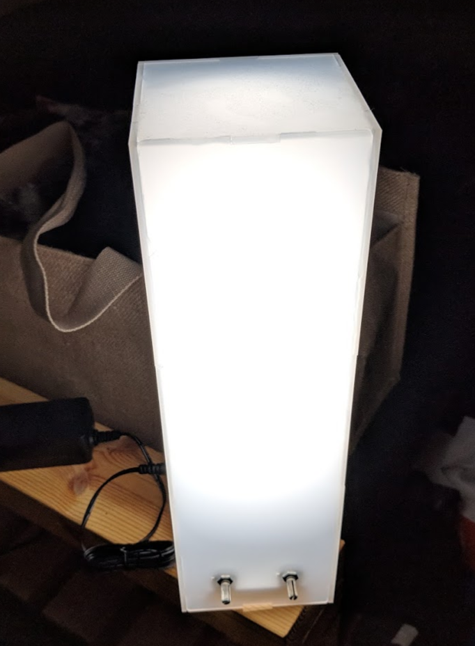
Final result!
Happy making!
KiCad Files:
https://github.com/matthewlai/UnnaturalLight/tree/master/hardware
Arduino Firmware:
https://github.com/matthewlai/UnnaturalLight/blob/master/firmware/controller/controller.ino