Designing a 13A Arduino Motor Shield
What does it take to design a 13A constant-current/torque Arduino motor driver shield?
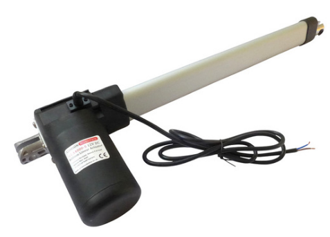
I am currently working on a tensile strength testing rig that will be detailed in a future post, but as part of that project, I need an Arduino shield that can drive a 12V/13A linear actuator. Electrically speaking, linear actuators are just DC motors. However, because I need to be able to drive the motor at constant current, I also need very fast current sensing and switching.
My requirements:
- 13A continuous
- High speed current sensing (about 5 microseconds latency)
- High speed switching (no significant switching losses at 100kHz)
First, a bit of theory. With brushed DC motors, there are two important and very simple equations –


These apply to ideal motors, and real motors are quite a bit more complicated, but these equations are good enough for what we are trying to do here. The important thing to pick up is that if we want to run a motor at constant speed (at no load), we apply a constant voltage. If we want to maintain a constant torque, we apply a constant current. This is why we need constant-current drive, to be able to control the force on the material under test.
If you are not familiar with the basics of motor driving or pulse-width modulation (PWM), I recommend checking out my post on that topic first.
As a reminder, here is the basic motor control circuit:
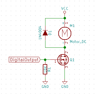
The motor M1 is controlled by N-MOSFET Q1 acting as a switch. R1 is a pull-down resistor to keep the gate turned off when the gate isn’t being driven (microcontroller in reset, during power-up, or if the microcontroller hasn’t been programmed yet). D1 diode is for flyback protection – motor coils are inductive, so when they are switched off suddenly, they will try to continue pushing current through the MOSFET, by generating a very high voltage, and that will often destroy the MOSFET. With D1 across the motor, the motor will drive the current through D1 instead.
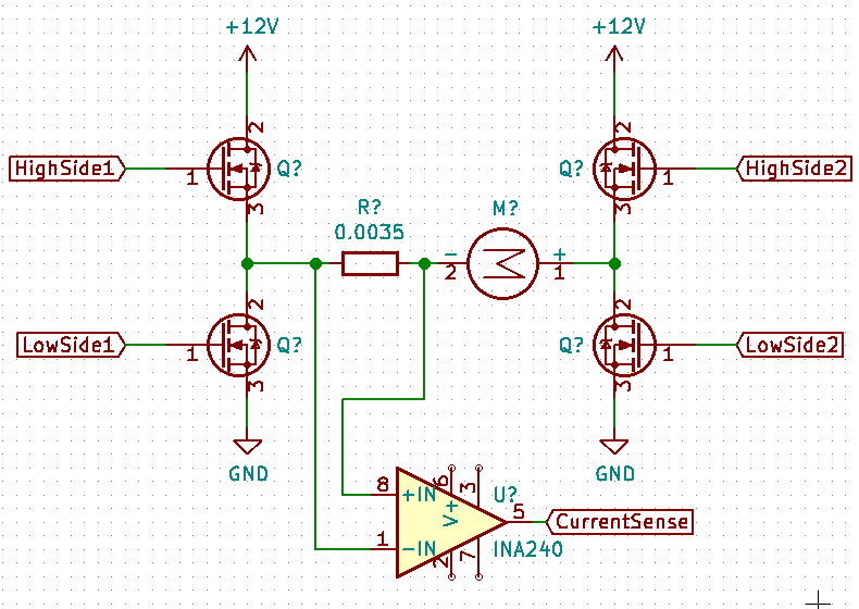
Because I need to drive the motor in both directions, I need something a bit more complicated – something called an H bridge.
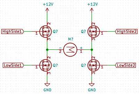
Here we have 4 control signals. To run the motor in one direction, we activate HighSide1 and LowSide2. To run it in the opposite direction, we activate HighSide2 and LowSide1. Not all control input combinations are valid – if we turn the MOSFETs on the same side on at the same time, they would short the power supply. So we have to make sure we don’t do that in software, and have a fuse in the circuit as a last line of defence in case a bug in the firmware causes us to do this.
Aside: If you studied the H bridge circuit in university, you have probably seen it with P-MOSFETs on the high side, because they are easier to switch in that configuration. With N-MOSFETs on the high side, you need to apply higher than supply voltage to turn the gates on. However, in real life, almost everyone use 4 N-MOSFETs nowadays, because they tend to be more efficient (lower Rds(on)) than P-MOSFETs built with the same technology. The high voltage required to turn the high FETs on is usually supplied by a charge pump, usually integrated into the driver IC.
The last step is to add current monitoring, both so we can do constant-current drive, and also so we can detect when the motor is stalling. There are many ways to do it, but the most common way is to add a shunt resistor (a very small resistor in series with the motor), and measure voltage across that. The voltage is often very small, because having larger voltage here means the resistor will be wasting more power. So we usually also need an amplifier.
This application is so common that they actually make special-purpose resistors and amplifiers for them – current-sense resistors and current-sense amplifiers. I picked 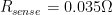
- We want the resistance to be as high as possible to reduce the gain needed on the amplifier, because the amplifier will amplify noise as well.
- We want the resistance to be as low as possible so we are not wasting a lot of power on the resistor (and even worse – having to heatsink it!)
With

And

Why 2.275V? Because our Arduino has an analog input range of 0 – 5V, and if we design the circuit to make the mid-point (zero-current point) 2.5V, having a 2.275V range means we are mapping [-13A, 13A] to [0.225V, 4.775V], which is roughly the output range of the amplifier (Datasheet, Page 6, “Swing to Vs power-supply rail” and “Swing to GND”).
Here is what our (simplified) circuit looks like now:
The last piece of the puzzle is to drive the gates from Arduino outputs. We can’t just connect them directly to the gates, because:
- Arduino only outputs 5V, which is enough for the low FETs, but not the high ones, which require about 18V in our application.
- Arduino outputs have low current capacity and won’t switch the gates fast enough, which means the FETs will spend more time in the “saturation region” (when they are in the process of getting turned on or off), and FETs dissipate a lot of power in this state.
So we want to use gate driver chips. There are many gate drivers to choose from, but MC33883 is exactly what we need. It can drive the gates quickly, and also generate the 18V (or so) required to drive the top N-MOSFETs.
This is basically the example application circuit given in the datasheet:
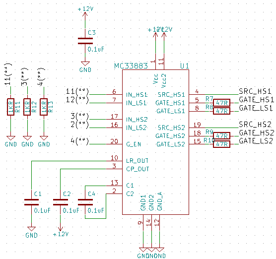
The 
The numbered signals go to the corresponding Arduino pins.
That’s it really!
PCB Design
On the PCB design side, this circuit is reasonably straightforward, but there are a few things to be careful with.
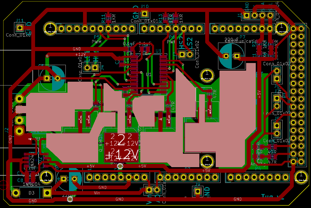
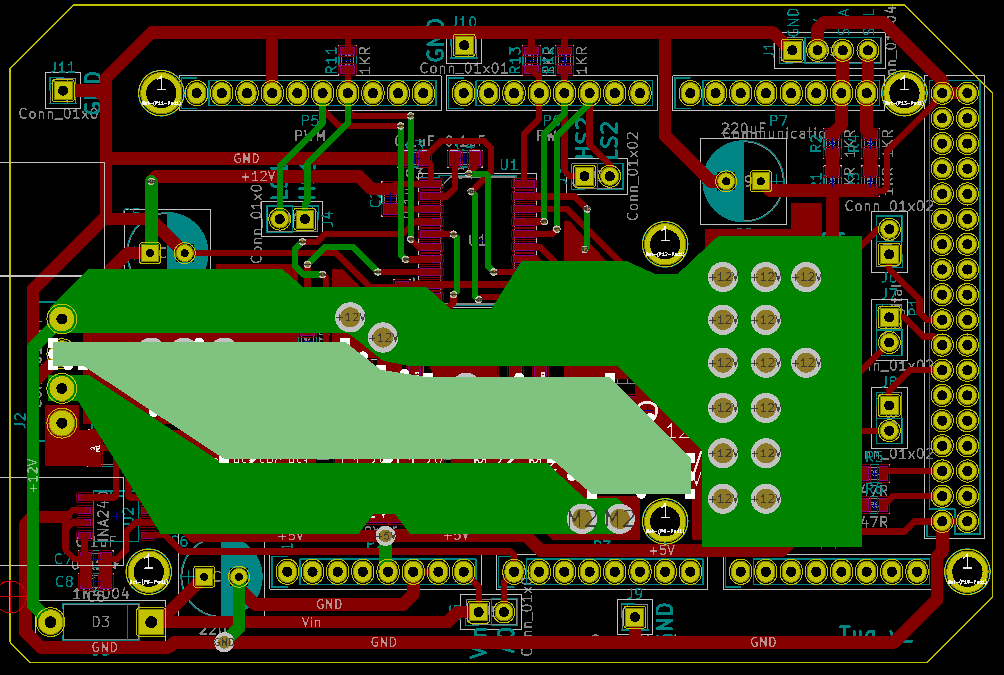
- Traces carrying the motor current need to be very wide. 13A is a lot of current for PCB traces. Here is a calculator. In this design I actually used fill zones for these traces, to make them as big as possible. Fill zones are a very good tool for designing high current circuits in small space. The highlighted zones are the high current traces:
- Front:
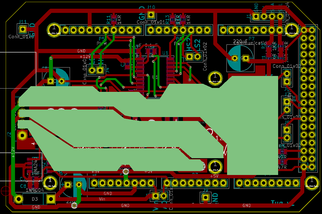
- Back:
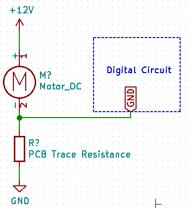
- Another thing to think about is grounding, in particular, the problem of grounds stop being grounds. The motor will be dumping quite a lot of current into the ground through the MOSFETs, and that multiplied by trace resistance means some parts of the ground traces will actually be at a higher voltage! It causes problems if we connect digital ground to the lifted parts of the ground conductor, because all our signalling is ground-referenced, and when different parts of the circuit sees ground at different potentials, they will have trouble talking to each other.
- Illustration (here “Digital Circuit” sees a higher ground due to PCB trace resistance and all the current the motor is dumping through the trace):
- The solution is to have all the different parts of the circuit connect to ground in a star configuration – only connected together at one point, where the ground conductor enters the board. This is how I implemented it on this board:
- Ground for the motors:
- Ground for the rest of the circuit (digital stuff):
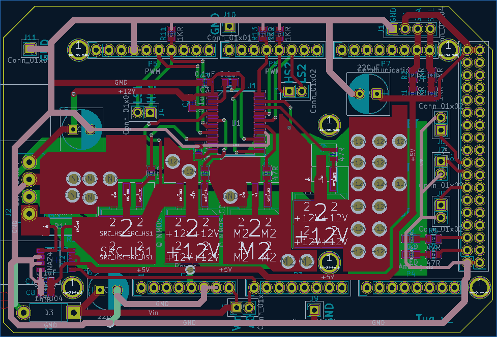
- There are a few places where the motor ground and digital ground are very close on the right side, and it would seem like I can save quite a bit of routing by just connecting digital grounds on the right side to the motor ground, but that would be a bad idea. This star configuration gives digital circuitry nice and clean ground to work with. Also notice how the ground for the digital circuitry is split into two branches – one along the top of the PCB, and one along the bottom. They aren’t connected together because that would create a ground loop, where it will act as an antenna to either receive or radiate noise. This probably wouldn’t be a problem in reality in this design, but it’s good practice to keep the star a star.
- Add test points! This is not specific to this project. It’s very easy to add test points during design, and much harder to find places to probe hard-to-reach signals when you need to debug a design that isn’t working. All the 2-pin headers in this design are test points. I have test points on the various supply voltages, input signals to the gate driver, and output of the current sense amplifier.
That’s all folks! In the next post we’ll talk about using an oscilloscope to verify that all the signals look like what we expect.