Simulating Sunrise/Sunset For My Aquarium
I designed a pretty and dynamic light for my aquarium!
Why?
This is what I started with:
 build-up, which I have since decided to filter out.](/images/wp-content/uploads/2020/08/IMG_20200327_164146-2-450x340.jpg)
Original setup. The green tint is due to tannin build-up, which I have since decided to filter out.
It’s… fine, but the lighting left a lot to be desired. Lighting is not just aesthetic – those are real plants, and plants require light for photosynthesis. A lot more light than most people imagine! In a tank of this size, with plants with moderate light requirements, it’s generally advisable to aim for about 40-50W in LEDs (or ~3000 lumens, if we want to get technical). If you have worked with LED lighting before, you probably think 40-50W is an absurd amount of light for such a small space (equivalent to about 400-500W incandescent), and you would be right.
I initially got two of these lights. Advertised for either 18W or 25W each, depending on whether you trust the title or the description.
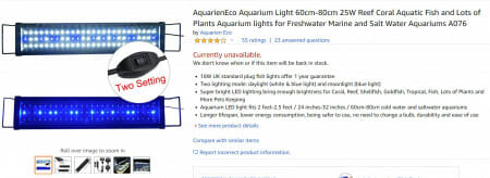
Original lights
I grew suspicious, and measured the power draw at the wall – 15W each. With a 80% efficient power adaptor. That means I was really only getting about 12W each. Not nearly enough! I did what any self-respecting engineer would do and left a review on Amazon. So I needed new lights, and instead of taking my chances with another cheap and probably falsely advertised light, I decided to just take it into my own hands, and make a much nicer one. MakeColourTexture
Design Decisions
What kind of lights to use? I originally planned on building my own out of COBs. But that proved expensive, and I would need to sort out lenses myself and that’s a lot of work.
Instead I decided to go with MR16 (GU5.3) lights. They run on either 12VDC or 12VAC, and are widely commercially available, and there are dimmable versions… sort of.
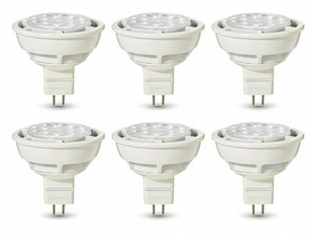
MR16/GU5.3 lights
The low voltage is important because I don’t want to kill myself or my fish if any part of the system falls into the water. Unfortunately this rules out the Philips Hue, which would have made this project 10x simpler.
I ended up deciding on 4x 2700K 8W warm white and 4x 6000K 6W cool white lights.
There are no smart 12V LED lights, so I had to build my own controller.
Controller
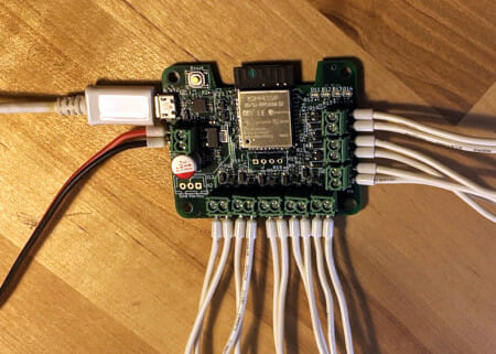
The controller
ESP32-based so it can be controlled remotely (and firmware upgraded remotely!), and also automatically sync time. As it turns out, keeping accurate time locally, at low power, and over extended time, and at low cost, is a pretty difficult problem. Since we need WiFi anyways, I decide to not bother with that, and just have it sync with an NTP server every day. This way I also don’t need to worry about having a way to set the current time, which we need the current time to do simulated sunrise/sunset.
See this follow up post for a deep dive on the electronics.
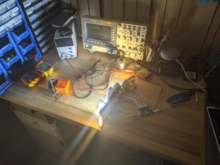
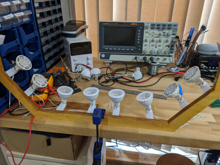
Testing setup. It is BRIGHT!
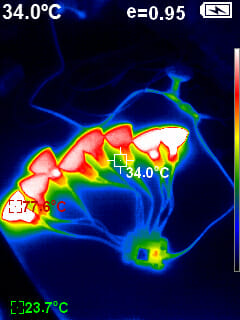
And in infrared
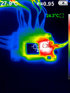
The switching MOSFETs aren’t getting hot at all, but the 3.3V regulator powering the ESP32 is. It was going up to 70C before I downclocked it from the default 240 MHz to 80 MHz.
The Frame
… is cut out of plywood with a jigsaw. And I am not very good with jigsaw. Oh and a few coats of yacht varnish for waterproofing just in case.
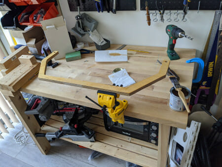
The plywood frame
I would have design a more organic shape and laser cut it instead, but I no longer have access to a laser cutter thanks to COVID-19 (just Google it if you are reading this decades from now and don’t know what I am talking about… and Google was a popular search engine in the 2020s… use whatever is popular now), so I had to cut it out with a jigsaw like a pleb.
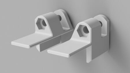
Feet so it can stand on the aquarium. Designed in Fusion 360 and printed on my trusty Prusa
Printed some brackets to mount the MR16 fittings to the frame.
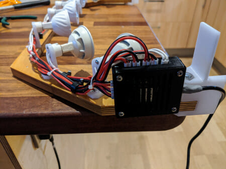
And with the electronics mounted. Also in a printed case. Lots of wire extensions involved, but heat shrink solder sleeves made it a very easy job. Also free waterproofing!
Result
As you can see in the video at the beginning of the post, it worked out quite well. The lights don’t dim as much as I had hoped, and I may be designing a new controller in the future that does AC chopping (which is probably what the lights need) for better dimming, but otherwise, it turned out almost exactly as I had envisioned, so I am pretty happy about that.
Files
All files below are hereby released under CC BY-SA.
KiCad files: https://github.com/matthewlai/WiredHut/tree/master/hardware/light_control/light_control
esp32-arduino firmware: https://github.com/matthewlai/WiredHut/tree/master/firmware/fishtank_light/main
Fusion 360 model for the legs: https://a360.co/3abuvg5